As part of our feature series on safe machine design, Euchner’s Mark Staples answers some questions on the ISO 14119:2013 machinery safety standard and the procedures for the selection of a suitable interlocking or guard locking device.
What does the standard contain?
The standard describes the selection and usage of interlocking devices with/without guard locking on safety doors, safety covers and other movable safety guards.
The term interlocking devices refers to safety switches fitted to safety doors that ensure machines/systems safely shut down on opening the door. Interlocking devices with guard locking (guard locking devices) only enable access once the risk of injury is eliminated (e.g. the hazard due to over-traveling machine movements, or machine rundown time due to inertia of moving parts, which could be something as simple as a rotating cutting blade).
The standard’s application, like all safety-related standards of this type, gives machine designers an assurance that the requirements of the Machinery directive are met.
Can it be used to obtain UKCA or CE marking?
To assign UKCA or CE marking to a machine/system, the law as applicable to machinery permits various possibilities, one of which is the use of harmonised standards. If all relevant standards are applied, ‘Presumption of Conformity’ can be assumed. One harmonised type B standard is ISO 14119, which is applicable independent of the machine type for the usage of safety switches on safety doors. Machine builders may find it difficult to defend themselves if applicable standards have not been followed and accidents occurred because of this.


What are an interlocking device’s component parts?
The standard defines the term ‘interlocking guard’, which includes the movable safety guard and the interlocking device. This generally has two parts, the actuator and position switch.
What are the guard locking principles?
ISO 14119 contains four principles of operation for guard locking devices:
1. Spring applied – Power-ON released
This is a closed-circuit current principle in relation to the function of guard locking. It means that guard locking devices are moved to the ‘locked’ position by a spring on the removal of the power. Switching on the power opens the guard locking device.
2. Power-ON applied – Spring released
This principle operates in the opposite manner and is referred to as ‘electrical guard locking’. It’s an open-circuit current principle.
3. Power-ON applied – Power-ON released
This is a principle that doesn’t change position on the removal of power. It’s also called the bistable principle. Power must be applied to change it to the other state. As the removal of power doesn’t change the position of the guard locking device, it’s considered a closed-circuit current principle.
4. Power-ON applied – Power-OFF released
This corresponds to an open-circuit current principle as the guard locking device opens on the removal of the power. Typically used for electromagnets, e.g. on the CEM.
Which principle must be selected?
It’s possible to select from these options for the operation of the guard locking. Two of these are closed-circuit current principles where the guard locking device is closed (locked) in the event of a power failure. A guard locking device for personnel protection must use one of these two principles.
The standard permits a minor exception from this selection only if it can be shown that a closed-circuit current principle is an unsuitable method. The evidence for this will be very difficult to find. Often an open-circuit current principle is chosen for the access to the machine in the event of a power failure. However, this aspect can also be ensured using a closed-circuit current principle guard lock with an emergency release mechanism.
For process protection designers are free to decide which type of guard locking is selected as it doesn’t represent a safety function. The only requirement is that on guard locking devices for process protection, the safety of the interlocking device must not be degraded.
How must a guard locking device be controlled and how is the PL of the circuit determined?
The greatest change in ISO 14119 compared to its predecessor is the requirement to consider the control of guard locking as a safety function. This doesn’t mean that a guard locking device must always be controlled with dual channels with immediate effect, only that a risk analysis must be undertaken to determine the necessary PL.
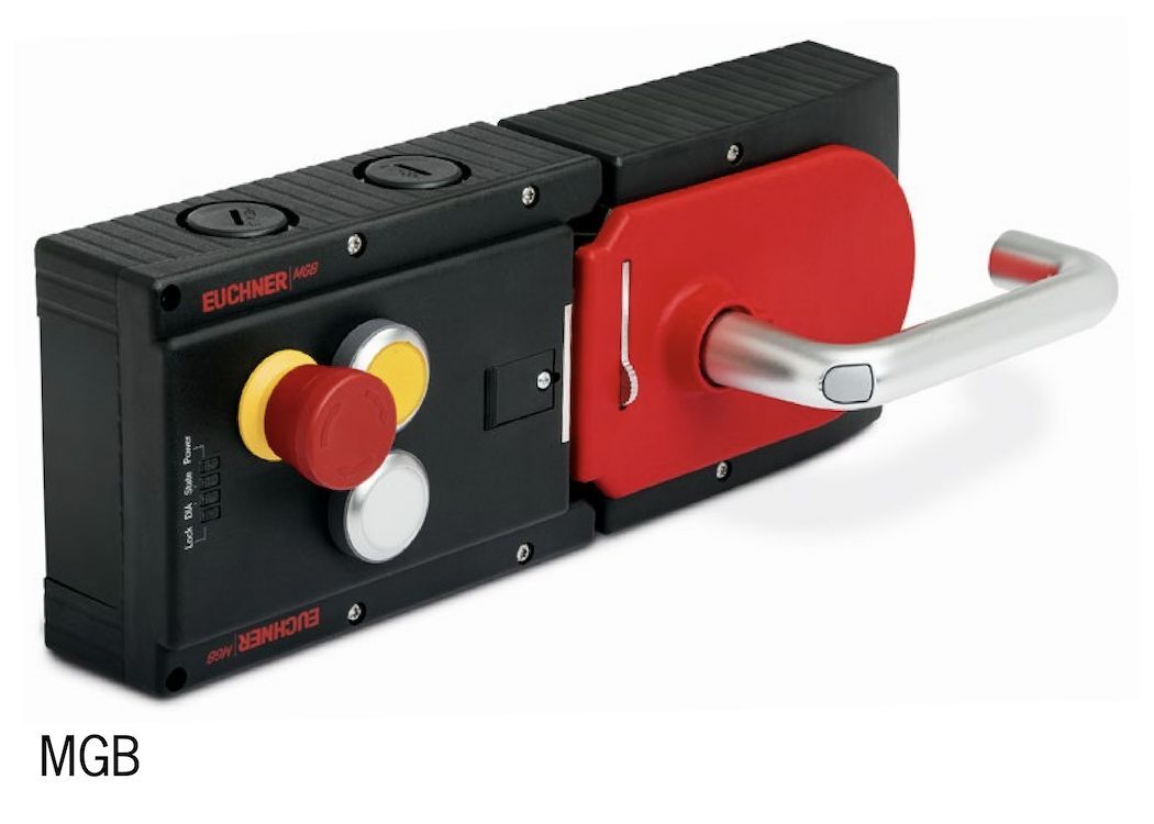
Guard locking devices like Euchner’s MGB function differently. These devices have a permanent power supply and the control of the guard locking is undertaken via inputs. Therefore, guard locking is not fully de-energised even on shutting down the two inputs. On these devices, the electronics contribute to the probability of failure of the control chain and a block must be added to the PL calculations.
Is the series connection of electromechanical guard locking devices safe?
Series circuits can be used without problems up to category 1. The situation becomes difficult if diagnostics on the individual safety switch is necessary. The problem here is that with a series connection, faults are masked by other safety switches. Unfortunately, this aspect is often overlooked and can lead to even relatively new equipment having guarding faults going undetected.
Euchner (UK)
T: 0114 256 0123


